Lesson 7: Using Sensors with Arduino

So far in the class we have only covered topics related to sending and receiving data over the serial interface of the Arduino with our first projects where we were learned some basic algorithms. We have also learned how to blink LEDs and turn LEDs on and off.
Last week we learned how to use the first and simplest of the sensors, a push button to activate a walk light on a simulated intersection. This week we are going to learn about some of the active sensors that came in our kits and do one of the first projects using an active sensor.
Pulse Sensors
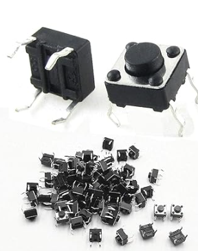
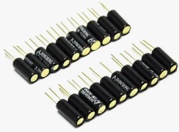
We have three pulse type sensors in our kits, the first is the simple push buttons
Second we have a tilt ball switch.
Third we have sensor we plan to use this week is the “HC-SR04” which is a really neat sensor that can be used to measure distances and detect objects. We will be using it in an object detection way, but I will describe in detail how to use the sensor.
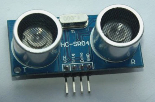
The HC-SR04 is actually a simple device. It utilizes sonar to measure the distance between the sensor and an object in front of it. Well technically, it measures the amount of time it takes to hear its own sound wave bounce back from the object in front of it. One of the “eyes” is a speaker that emits an ultrasonic tone and the other “eye” is a highly sensitive microphone that picks up the echo response of the speaker output.
You will notice that the sensor has four pins.
| Pin | Purpose | Arduino Code Needed |
| VCC | Power (5V) | None, but you can connect it to the 5V pin on the Arduino or an external supply. |
| Trig | Sends the tone | //define the trigger pin const int trigPin = 9; //(2-13) //initialize the pin in setup pinMode(trigPin, OUTPUT) //send a pulse signal in the loop digitalWrite(trigPin, LOW); delayMicroseconds(2); digitalWrite(trigPin, HIGH); delayMicroseconds(10); digitalWrite(trigPin, LOW); |
| Echo | Receives the echo back | //define the echo pin const int echoPin =10; //(2-13) //define the duration and distance float duration, distance; //initialize the pin in setup pinMode(echoPin, INPUT); //in the loop we set a timestamp when it gets a signal duration = pulseIn(echoPin, HIGH); //calculate the distance distance = (duration*.0343)/2; |
| GND | Ground PIN completes the circuit | No code, but can be connected to the Ground Pin of the arduino. |
So to explain a couple of the lines above the first one you need to know about is a new Arduino command pulseIn() which tells the arduino you want to know how much time passed between when the function was called and the pin went HIGH or LOW, depending on what you are trying to read. In the case of the sonar sensor we want to read HIGH.
So we use the line duration=pulseIn(echoPin, HIGH); which will result in a floating point number which counts the time in microseconds it is waiting for an echo of the pulse. So how do we get a distance from the time?
For this we need to know a little bit about physics and the speed of sound. The speed of sound is approximately 340 meters per second, but since we get the time returned in microseconds we need the speed of sound in microseconds and it is best to get the distance in centimeters so a quick google search tells us the speed of sound is 0.0343 cm/micro-second. That is were the multiply by 0.0343 comes from. Now of course we have to divide that distance by two because it measured the travel time of the pulse which was from when it left the sensor until it returned so we get double the distance.
distance = (duration *0.0343)/2;
So for a full example of the code to use the sensor connected to pins 9 and 10, it would look like this and it would print to the serial console the distance the sensor is away from an object.
/*
* HC-SR04 example sketch
*
* https://create.arduino.cc/projecthub/Isaac100/getting-started-with-the-hc-sr04-ultrasonic-sensor-036380
*
* by Isaac100
*/
const int trigPin = 9;
const int echoPin = 10;
float duration, distance;
void setup() {
pinMode(trigPin, OUTPUT);
pinMode(echoPin, INPUT);
Serial.begin(9600);
}
void loop() {
digitalWrite(trigPin, LOW);
delayMicroseconds(2);
digitalWrite(trigPin, HIGH);
delayMicroseconds(10);
digitalWrite(trigPin, LOW);
duration = pulseIn(echoPin, HIGH);
distance = (duration*.0343)/2;
Serial.print("Distance: ");
Serial.println(distance);
delay(100);
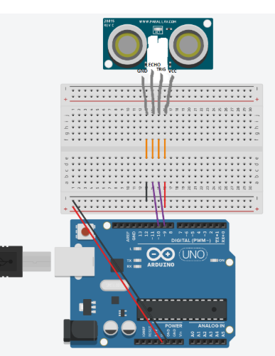
}Here is a wiring diagram for the code above:
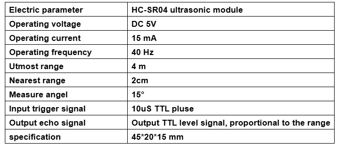
It may be important as you combine it with other sensors to know the electrical parameters, so you don’t overload your Arduino or your power supply.
Resistive or Voltage Level Sensors
These are sensor that utilize the analog input pins on the Arduino, of which we only have five, so there is a limit to how many of these we can use at a given time.
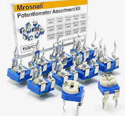
The simplest of these is the potentiometer.
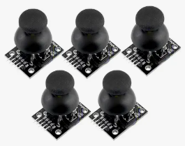
Then we have a joystick module which is really just two potentiometers and a push button. So once you learn how to use the potentiometer programming the joystick will be a breeze.
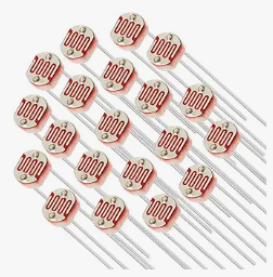
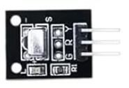
We have some active resistance based sensors the first is the photo-resistor which changes resistance based on the amount of light it is exposed too.
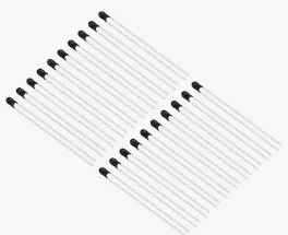
We also have a thermistor which is a device that changes resistance based on the temperature.
Digital Sensors
The final type of sensor is probably one of the easiest ones to program, because it sends a digital signal to the arduino which we can simply read the values from. We can build most of these using the previous sensor types ourselves, but these make it possible to do more with the Arduino as it is freed up to just read values instead of, for example calculating the temperature based on the resistance of the thermistor.
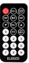
The first digital sensor we will talk about is the IR Receiver Module, it is paired with a remote control and allows you to determine which button was pressed on the remote.
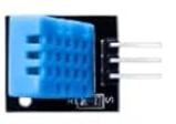
The second is the temperature and humidity sensor.
We will discuss how to read these digital sensors next week in class. Maybe you can give some thought into what you think we can build using some of them.
Homework this week
(1) In our project for next week, you will see if you can figure out how to turn on your walk signal light when an object comes close to the sonar, when I built it I picked using an object within 5 cm of the sensor to turn on the light, you can pick whatever you want. The sensor claims it can measure anything between 2cm and 4 meters.
(2) Come up with some ideas for how we can use the other sensors in our kit to do something fun. I would like to hear your ideas and we can pick a project to do together as a class, or you can work on something of your own.
Next week we will learn about the actuators in your kit and how to make the Arduino do a little bit more than just turn on lights or write information on the serial port.