Lesson 9 – Self-balancing Robot

Sorry but you are on your own for a robot frame. you have two motors in your kit, you can actually do this with one motor if your frame is stable enough, but I recommend using two motors as you will get more torque allowing for faster response time when the robot starts to fall.
You can scale this up using larger motors and larger batteries and make a hover board or Segway with the same concepts.
We will be using the sonar sensor to measure a change in distance of the sensor from the ground to let us know if the robot is shifting from an upright position. You can use the same code from the Thermin project in Lesson 8 to figure out if the robot is leaning. In my sample circuit design I am using different pins for the sonar though so you will need to rewire it.
There is also a possibility that you can wind up with crossed wires on the two motor and the robot will spin and fall instead of correcting it’s balance, you can change it by moving wires, or modifying the motor direction code to compensate.
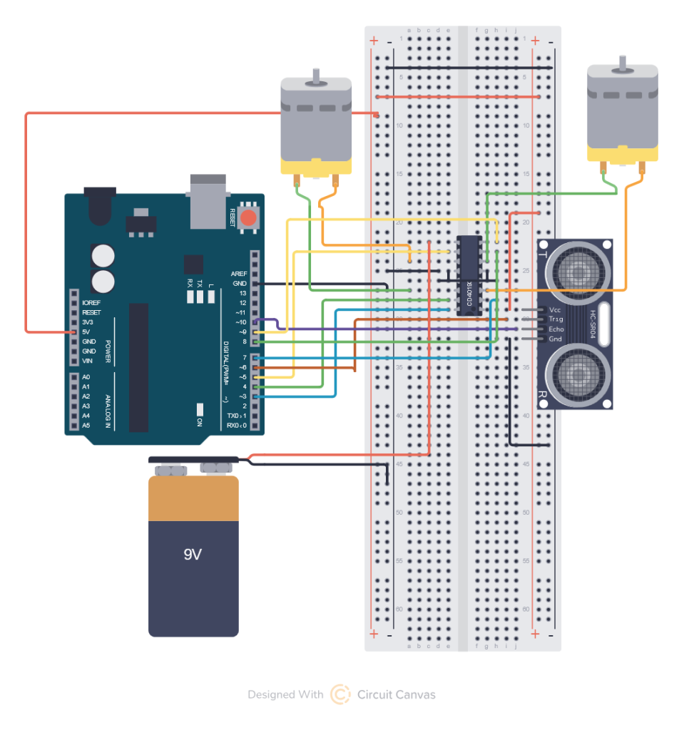
You can find the circuit below, the tool I used did not have the correct IC so I pick a random one with the same number of pins, you should be using the L239D from your kit, (the h-bridge motor controller).
The L239D has the following pin-out:

We will wire it this way in our project
| IC PIN | Arduino Pin |
| Enable 1,2 (1) | Pin 3 |
| Input 1 (pin 2) | Pin 4 |
| Output 1 (3) | left motor one wire |
| GND (4) | GND |
| GND (5) | GND |
| Output 2 (6) | left motor other wire |
| Input 2 (7) | pin 5 |
| Vcc2 (Vs) (8) | 9V positive |
| Enable 3,4 (9) | pin 9 |
| Input 3 (10) | pin 7 |
| Output 3 (11) | right motor one wire |
| GND (12) | GND |
| GND (13) | GND |
| Output 4 (14) | right motor other wire |
| Input 4 (15) | pin 8 |
| Vcc1 (Vss) (16) | 5VDC |
The HC-SR04 Sonar sensor connects as follows:
| PIN | Arduino Pin |
| +Vcc | 5VDC |
| Trig | pin 6 |
| Echo | pin 10 |
| GND | GND |
Above you see the best drawing I could pull off for the circuit. I think my example works but I have a dead 9-Volt battery causing it to fail.
Because of the complexity of the circuit and the fact that if you want to make one you have to build a frame I am giving you my code below. Note that you may have to change the delay time or adjust lspeed and rspeed to make the motors respond fast enough depending on the weight of your frame. the lspeed and rspeed works from 0= motor stopped to 255 motor running full speed.
/* Comment block describing circuit
 *  GND goes to
 *  * pin 1 of HC-SR04
 *  * pins 4,5 11, 12 of L293D
 * 5V goes to
 *  * pin 4 of HC-SR04
 *  * pin 16 of L293D
 * For best performance
 *  * 9v goes to pin 8 of L293D
 * Digital pin 6
 *  * goes to TRIG of HC-SR04
 * Digital pin 10
 *  * goes to ECHO of Hc-SR04
 * Left Motor connects to
 *  * L293D pins 3 and 6
 * Right Motor connects to
 *  * L293D pins 11 and 14
 * Digtial pin 2
 *  * goes to L293D pin 2
 * Digital pin 3
 *  * goes to L293D pin 7
 * Digtial pin 4
 *  * goes to L293D pin 10
 * Digital pin 5
 *  * goes to L293D pin 15
 * Digital pin 9
 *  * goes to pin 1 (left motor PWM)
 * Digital pin 3
 *  * goes to pin 9 (right motor PWM)
 */

int trig=6;
int echo=10;
int lfwd=4;
int lrev=5;
int rfwd=8;
int rrev=7;
int lpwm=3;
int rpwm=9;
int lspeed=256;
int rspeed=256;
float prevdist=0;

void setup() {
  pinMode(trig,  OUTPUT);  //trigger pin
  pinMode(echo, INPUT);  //echo pin
  pinMode(lfwd, OUTPUT);
  pinMode(lrev, OUTPUT);
  pinMode(rfwd, OUTPUT);
  pinMode(rrev, OUTPUT);
  pinMode(lpwm, OUTPUT);
  pinMode(rpwm, OUTPUT);
  //Turn motors off to start
  digitalWrite(lfwd, LOW);
  digitalWrite(lrev, LOW);
  digitalWrite(rfwd, LOW);
  digitalWrite(rrev, LOW);
  Serial.begin(9600);
  prevdist=distance();
}

void gozero() {
  analogWrite(lpwm, 0);
  analoglWrite(rpwm, 0);
  delay(500);
}

void gofwd() {
  digitalWrite(lrev, LOW);
  digitalWrite(lfwd, HIGH);
  digitalWrite(rrev, LOW);
  digitalWrite(rfwd, HIGH);
  analoglWrite(lpwm, lspeed);
  analoglWrite(rpwm, rspeed);
  Serial.print("fwd=");
  Serial.println(lspeed);
  delay(500);

}

void gorev() {
  digitalWrite(lrev, LOW);
  digitalWrite(lfwd, HIGH);
  digitalWrite(rrev, LOW);
  digitalWrite(rfwd, HIGH);
  analogWrite(lpwm, lspeed);
  analogWrite(rpwm, rspeed);
  Serial.print(" rev=");
  Serial.println(rspeed);
  delay(500);
}

float distance(){
  //Serial.println("Starting dist measurement");
  float  duration, cm;

  digitalWrite(trig,LOW);
  delayMicroseconds(2);
  digitalWrite(trig,  HIGH);
  delayMicroseconds(5);
  digitalWrite(trig, LOW);

  duration  = pulseIn(echo, HIGH);
  Serial.print(duration);
  return duration; //returns  distance in centimeters
}


void loop() {
  Serial.print("PREVDIS=");
  Serial.print(prevdist);
  Serial.print(" NEWDIST=");
  float dis = distance();
  Serial.print(dis);
  Serial.print(" DIFF=");
  float diff = prevdist-dis;
  Serial.print(diff);
  // prevent runaway from bad angle read.
  //adjust speed based on lean angle big angle requires faster correction
  lspeed = 0;
  rspeed = 0;
  if (diff > 0) {
     gorev();
  }
  if (diff < 0) {
     gofwd();
  }
  if (diff = 0) {
     gozero();
  }
}
You can probably build a robot frame out of a cardboard box and tape the motors to the inside of the box. You can use any kind of scrap round lid a plastic one off of an older peanut butter jar works great and put a whole directly in the center, slide it on the motor shaft and superglue or hot glue it. You want the weight at the top the robot for a reverse pendulum effect, which although it seems it would be the opposite will cause the robot to fall slower giving it more time to respond. The taller the robot the easier it is to get it to balance. You also want to put the sensor as far from the center of the robot as possible pointing at the ground my design has it a little too close so it doesn’t respond to the motion of the fall as well as it should. I suggest using a 12 inch ruler and mounting the sensor to the end of it and making the robot about one foot tall as well, mine is much smaller so probably won’t work really well.
I will bring it to class on Friday and help you wire your circuits your project will be to attempt to get it on a robot frame of some sort.