Lesson 5 – Introduction to Arduino

The Hardware
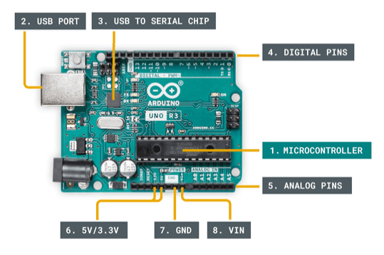
The Uno is the most widely known board that most people start off with when learning about Microcontrollers.
1. Microcontroller
The microcontoller can be thought of as the brains of the Uno board. Arduino is actually the name of this chip, which also has become the defacto name of all the boards manufactured by the company. You can buy just the chip and build your own devices based on the microcontroller without integrating entire board, but it gets a lot more complicated.
This component is the same as the CPU on your laptop, but less powerful as it does not have features for connecting to external memory, graphics cards, network cards, etc. When you write programs for the Arduino you are writing software to run on this device.
2. USB Port
The USB port is the primary method of connecting to the Microcontroller board it requires an extra chip on the board to convert the USB signals to a serial communication signal understood by the Microcontroller.
3. USB to Serial Chip
This is a critical component to make programming the microcontroller possible. It is a CH340 or CH341 chip which does two things, it adjusts the pulse width of the signals coming from the computer to match the timing of the microcontroller and it adjusts the voltage level from the 5V (TTL) logic signals coming from the USB to the lower level 3.3V signals needed by the microcontroller. Ironically on your laptop there is likely the same chip that converts the serial 3.3V signals coming from the CPU to the 5V (TTL) signals on the USB. Without this chip the voltage levels would break the microcontroller.
4. Digital I/O pins
These are the first pins you usually learn to use as you start programming an Arduino, they can be used to turn on and off LEDs and relays, read data from physical switches, and receive information from digital sensors. You can think of them as on/off switches when used as outputs and as readers for on/off switches when used as inputs. On the Uno there are 13 digital pins. They can also be used to control motor speeds by pulse width modulation, which we will learn about later in the class.
5. Analog pins
These pins are used to read analog signals, like voltage levels for example. They take an input value between 0 and 5 volts and utilize an Analog to Digital Converter to convert the voltage level to a 10-bit number which means a number between 0 and 1023. These pins are input only pins. The Arduino does not directly have analog outputs, but they can be simulated with pulse width modulation on the Digital pins.
6. 5V/3.3V pins
These are voltage output pins that can be used to power external sensors. There is a limit to the amount of power that can be drawn through these pins so sometimes it is better to power the sensors off of an external power source. The maximum current draw shared between all the voltage output pins is 50mA. This will suffice for a majority of the projects we will do in this course, but it is important to note that it is probably not really enough for driving motors.
7. GND
This is known as the ground pin, if you remember anything from last semesters course it is usually connected to the negative terminal of the battery or power supply and is the reference of what is considered zero volts on the system. While it is rare sometimes a device will use a positive ground and all the voltages on the system will be negative with respect the zero level. We will never do this in this course and you will likely never see this in any modern device. However, there are some electronics especially within classic cars and farm equipment which work on a negative ground so you need to be aware that it can happen.
8. VIN
This pin is where you would connect a power supply or battery pack if you don’t want to power your project from your computer via USB port. Some of our projects will use this port.
Basic Operation
The microcontroller is designed to run one task or sequence of tasks in a loop. This is quite different from a CPU which can handle running multiple tasks at the same time. These tasks are referred to as threads and your common CPU is multi-threaded whereas the microcontroller is single-threaded.
Think of it like a stack of index cards that have instructions on them, you can only read one card at a time and then place it back on the bottom of the stack. The microcontoller does this very well and will read and execute this “stack” of instructions usually over a time period of 1 micro-second or about 1,000 times a second.
Your computer is multi-threaded which means it can read through multiple stacks of instructions at the same time so it has more than one stack of index cards containing instructions. It can also process these instructions every micro-second.
Circuit Basics
An Arduino is not very useful without connecting it to some external components, though over the last weeks we have written a couple of math algorithms to learn basic code structure and they work, it is not the best use of an Arduino. They are designed to control things in their environment and to do this they need to connect to other electronics. This week we will start connecting our microcontroller to some simple devices.
These external circuits are usually described using something called a schematic diagram, those who took my Introduction to Digital Electronics
Electronic Signals
Three are two different types of electronic signals we will work with in this course when it comes to programming the Arduino, actually there are only two types of electronic signals anyway.
Analog Signals
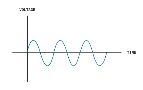
These can be structured waveforms like sine waves, triangle waves, and square waves, or random signals like the audio signal coming from your MP3 player or a microphone. They are plotted over time as the best way to understand analog signals. They can also be a constant voltage level that is not one of the standard digital logic levels of 5V, or 3.3V. In other words, we are looking at analog signals as signals where we care about more than just the presence or absence of a voltage. An example of an analog signal is the sine wave seen below.
Analog signals are more rarely used with microcontrollers because they are only capable of reading analog signals and are not very good at generating them.
Digital Signals
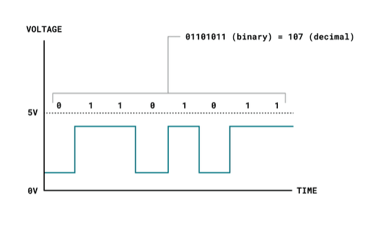
A digital signal can change over time just like the analog signal, but in a digital signal we only care about the presence or absence of the voltage. A voltage level between 4.5 and 5 volts is considered on, or one and a voltage below 0.7 volts is considered off or zero. These are the most widely used signals with microcontrollers, because they can both read and generate digital signals.
Sensors
There are several types of sensors available for the Arduino and we will be covering them over the next several weeks as we try to combine them to make interesting devices. Sensors can send either analog or digital signals and are connected to pins configured as input pins on the Ardunio.
Actuators
Actuators are the outputs from a microcontroller than can be as simple as lights, or as complex as position controlled motors. They are way more interesting than the outputs from a CPU in a computer because they interact directly with the physical world. The main actuators we will use in this class are LEDs and motors, but there are several other options out there to research.
You can find additional information on the Arduino and the basics here: Getting Started with Arduino | Arduino Documentation
Homework
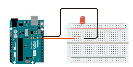
As you can see in the picture of the basic circuit above you can wire an LED with a 220ohm resistor to ground and the other end of the LED to one of the digital pins and control the LED blinking by defining which pin the LED is connected to in the sample “Blink” code below. In the wiring picture the LED is connected to PIN 13 so you will see the PIN number as 13 below, you can pick any pin you want and just change the number.
void setup() {
  // initialize digital MYLED Connected to pin 13 as an output.
  int MYLED = 13;
  pinMode(MYLED, OUTPUT);
}

// the loop function runs over and over again forever
void loop() {
  digitalWrite(MYLED, HIGH);   // turn the LED on (HIGH is the voltage level)
  delay(1000);                       // wait for a second
  digitalWrite(MYLED, LOW);    // turn the LED off by making the voltage LOW
  delay(1000);                       // wait for a second
}
The homework assignment for this week is to build a traffic light control that controls two traffic lights (red, yellow, and green) LEDs to simulate an intersection. The rules are simple when light1 is red light 2 must be green, when light 1 is green light 2 must be red, and both lights must display yellow at the same time as they change between red and green. For a challenge you can try and add a button as an input pin to simulate a crosswalk button, which will turn both lights red at the same time.
The wiring is simple, but the code may be a little more complicated. You will simply wire an LED to each of six pins along with a resistor running to ground. You can find a similar project online already but it only controls a single traffic light on a timer and I am expecting you to be able to control two.