Lesson 5 Homework Answers

You were asked to build a traffic control light for an intersection last week so below you will find the breadboard diagram for how your circuit should look, of course there are different ways of doing it, so if you did something different that works, then good job.
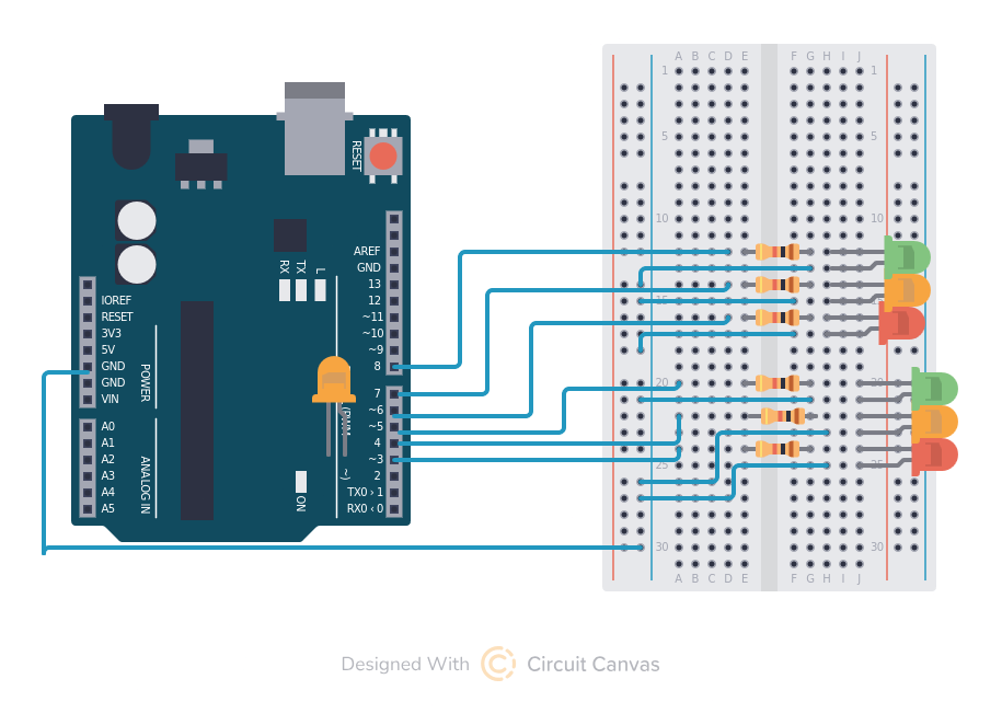
I apologize for the traffic light patterns being upside down from a normal traffic light, it is the only way I could draw the circuit to match my code without crossing wires and making it hard to read, you can cross wires when you build it and put the lights in the correct order.
Now the for the tricky part, it is fairly easy to make the circuit and get lights to come on, the hard part is making them come on the way you want. Your traffic light will have three “states”
- Top light red and bottom light green
- both lights green
- Bottom light red and top light green
In order to do this you will create a loop that contains the sequence of traffic light states and a delay between state changes.
int red1 =3;
int yel1 = 4;
int grn1 =5;
int red2 =6;
int yel2 =7;
int grn2 =8;

void setup() {
  pinMode(red1,OUTPUT);
  pinMode(yel1,OUTPUT);
  pinMode(grn1,OUTPUT);
  pinMode(red2,OUTPUT);
  pinMode(yel2,OUTPUT);
  pinMode(grn2,OUTPUT);
}

void loop() {
    //bottom light red
    digitalWrite(red1, 1);
    digitalWrite(yel1, 0);
    digitalWrite(grn1, 0);
    digitalWrite(red2, 0);
    digitalWrite(yel2, 0);
    digitalWrite(grn2, 1);
    delay (2000);
    //both yellow
    digitalWrite(red1, 0);
    digitalWrite(yel1, 1);
    digitalWrite(grn1, 0);
    digitalWrite(red2, 0);
    digitalWrite(yel2, 1);
    digitalWrite(grn2, 0);
    delay (1000);
    //top light red
    digitalWrite(red1, 0);
    digitalWrite(yel1, 0);
    digitalWrite(grn1, 1);
    digitalWrite(red2, 1);
    digitalWrite(yel2, 0);
    digitalWrite(grn2, 0);
    delay (2000);
    //both yellow
    digitalWrite(red1, 0);
    digitalWrite(yel1, 1);
    digitalWrite(grn1, 0);
    digitalWrite(red2, 0);
    digitalWrite(yel2, 1);
    digitalWrite(grn2, 0);
    delay (1000);
}
For next week maybe challenge yourself a little and see if you can figure out how you can add a white “walk” light and a button to activate the “walk” light turning both lights red while the walk light is on.
I will give you a hint, to make it work like a real traffic light at an intersection you will need to learn about a little more complex topic called an interrupt. An interrupt is exactly what it sounds like. Your computer program is running along doing it’s own thing turning your traffic lights on and off and you press the button. This Interrupts the program and tells it to do something else and then go back to it’s normal task.
An interrupt needs to happen as quickly as possible so you usually do something like set a variable “buttonpressed” to true, which causes your loop to do something different. I will show a quick example below. Making a different light come on for 1 second after a button is pressed.
int red1 =3;
int yel1 =4;
int button = 2;
volatile bool buttonPressed = false;
void setup() {
  pinMode(red1,OUTPUT);
  pinMode(yel1,OUTPUT);
  pinMode(button, INPUT_PULLUP);
  //this tells the arduino to treat pin 2 (the button) as an interrupt action.
  attachInterrupt(digitalPinToInterrupt(button), handleButtonPress, FALLING);
}

void loop() {
  if (buttonPressed) {
    //when the interrupt button is pressed turn red light off and yellow on
    digitalWrite(red1, 0);
    digitalWrite(yel1, 1);
    delay (1000);
    //tells the program we completed processing the interrupt.
    buttonPressed=false;
  }
  //normally red is on and yellow is off.
    digitalWrite(red1, 1);
    digitalWrite(yel1, 0);
}

//this code starts the interrupt process.
void handleButtonPress() {
    buttonPressed=true;
}